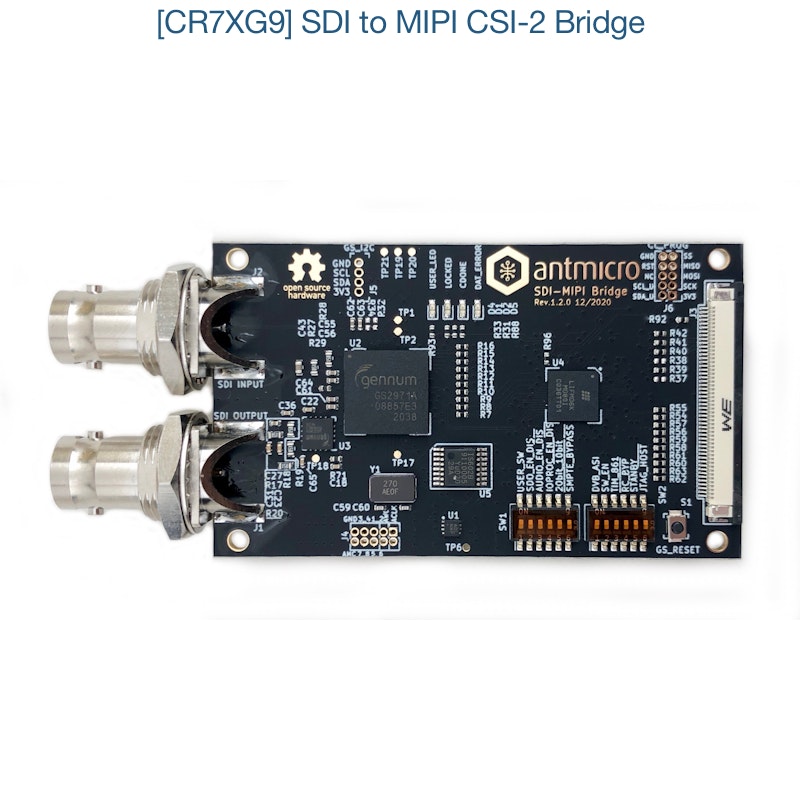
SDI to MIPI CSI-2 Bridge
In partnership with Antmicro, Capable Robot is pleased to offer their SDI to MIPI CSI-2 Bridge for purchase.
Antmicro offers hardware customization and software services around this converter, and Capable Robot can manufacture such custom variants.
Open Hardware
This product is licensed under the Apache 2.0 License and all sources are available in the Antmicro GitHub Repository.
Summary
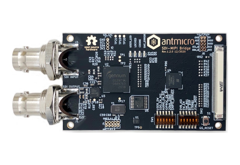
This device enables connecting industrial and filmmaking cameras and video accessories to platforms which include the MIPI CSI-2 interface.
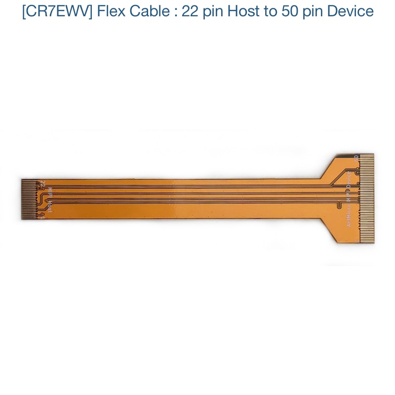
The board has an input BNC connector which accepts the SDI signal and Antmicro’s standard 50-pin FFC output connector (compatible with the Jetson Nano / NX Baseboard and other open hardware boards from Antmicro), which exposes MIPI CSI-2 lanes and an I2C bus for board configuration.
SDI signal conversion is implemented with a Semtech GS2971A deserializer which passes the parallel 10-bit video data to the Lattice CrossLink LIF-MD6000-6KMG80I. The CrossLink IC includes programmable logic and dedicated MIPI D-PHY transceivers. It can be configured to accept parallel video data from the deserializer and transmit it over MIPI CSI-2 to the host platform. SPI and I2C programming interfaces are exposed so the deserializer and CrossLink programmable logic device can be configured from the host platform.
Hardware Features
- Implements Single Link (3G-SDI) video conversion.
- Supports SMPTE ST 425 (Level A and Level B), SMPTE ST 424, SMPTE ST 292, SMPTE ST 259-C and DVB-ASI as defined by the Semtec GS2971A specification.
- Integrated loopback BNC connector for easy daisy-chaining with multiple SDI video accessories.
- Audio de-embedder for 8 channels of 48kHz audio exposed on I2S 10-pin header.
- Two 4-lane MIPI CSI-2 interfaces with up to 6 Gbps, each exposed on the 50-pin FFC connector. Note, current FPGA bitstreams only support one MIPI CSI-2 interface.
- I2C configuration interface for CrossLink FPGA bistream loading and SDI deserializer configuration (via I2C to SPI bridge IC).
- 12x DIP switches to initially configure the deserializer.
- LED state indicators.
Available FPGA Bitstreams
The following FPGA Bitstreams are available for download.
- 1080p60 YUV422
- 1080p30 YUV422
- 720p60 YUV422
Bitstreams for additional video resolutions and frame rates are planned for the future.
The SDI to MIPI Bride does not have an on-board SPI flash IC, so the appropriate bitstream for your operating resolution & frame-rate must be loaded via FFC’s I2C interface by the Host CPU.
Revision v1.2.0 hardware (the currently shipping revision) has three “rework” wires added to the PCB allowing for I2C-based bitstream loading. The Schematic PDF has an annotation which describes this rework. Future hardware revisions of the SDI to MIPI Bridge will included these connections in the PCB and this rework will no longer be necessary.
Note that due to limitations within the CrossLink FPGA, changing video resolution requires loading different bitstreams. This can be done without a power cycle of the system, but it does take a few seconds to perform.
Switch Settings
The PCB includes two banks of two-postion switches which send low or high logic signals to various configuration pins of the GS2971A.
When the default in the table below is lowercase / normal-text, it is okay for the switch to changed by the end user. If the default value is in uppercase / bold-text, the default position must be maintained for proper device operation.
| Name | Default | Notes |
| USER_SW | off | Connected to PB6D input of Crosslink FPGA. |
| SDO_EN | on | Enable/disable to SDO output of the GS2971A, which is buffered and exposed on the 'SDI Output' BNC. |
| AUDIO_EN | on | Enables/disables audio extraction fuctionality of the GS2971A. |
| IOPROC_EN | on | Enables/disables signal processing features of the GS2971A like error correction and level conversion. |
| 20bit_10bit | OFF | Used to select the output bus width. Must be set low for proper operation on this board. |
| SMPTE_BYPASS | ON | When on, the GS2971A carries out SMPTE scrambling and I/O processing. When off, GS2971A operates in data-through mode. |
| DVB_ASI | OFF | Enables/disables DVB-ASI mode of the GS2971A. |
| SW_EN | OFF | When off, the default state of GS2971A's SW_EN pin is low. A rising edge (via switch or FPGA GPIO) will cause the GS2971A to re-lock on the input video stream. Generally not needed unless the video source has been externally switched between two sources. |
| TIM_861 | ON | When TIM_861 is HIGH, the GS2971A outputs CEA 861 timing signals (HSYNC/VSYNC/DE) instead of H:V:F digital timing signals. |
| RC_BYP | off | When on, the serial digital output is the re-timed version of the serial input. When off, the serial digital output is simply the buffered version of the serial input, bypassing the GS2971A's internal reclocker. |
| STANDBY | OFF | When on, the GS2971A is placed in a power-saving mode. No data processing occurs, and the digital I/Os are powered down. |
| JTAG_HOST | OFF | When on, the GS2971A's host interface port is configured for JTAG test. When off, the GS2971A operates normally. |