- Per-port USB data pair disconnects
- Per-port power monitoring & control
- 6A of 5V power regulation for downstream devices
- A suite of physical world IO (I2C, SPI, UART, GPIO)
- Open-source Python firmware
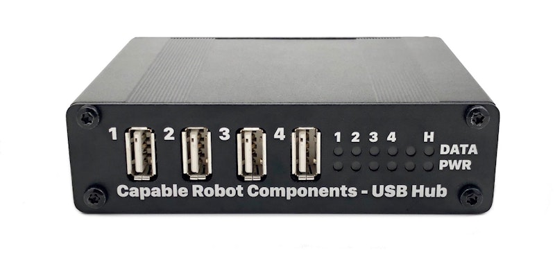
- 10x RGB LEDs showing data and power states of all ports
The Programmable USB Hub is perfect for embedded system development, hardware-in-the-loop testing, and use in industrial environments where highly-reliable USB communications is needed.
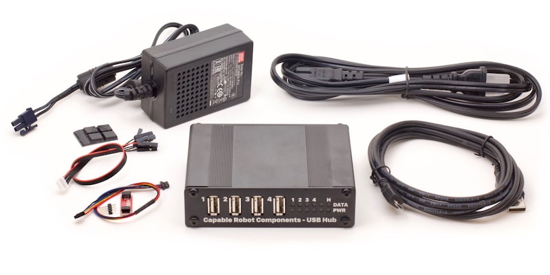
Programmable USB Hub Kit
The Kit includes everything you need to start using your Programmable USB Hub, including:
- Programmable USB Hub
- 24V 36W Power Supply with Molex MiniFit Jr
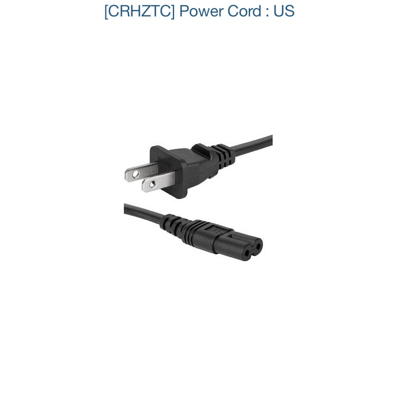
- Power Cord (US) - 1.8 m
- USB 2.0 A to micro B Cable - 1.8 m
- Auxiliary IO Cable (JST GH to 0.1" female headers) - 200mm
- I2C Qwiic Cable - 200mm
- Qwiic Adapter PCB
Programmable USB Hub
The Programmable USB Hub is fully assembled and tested.
Note that this SKU does not include power supply, USB cable, I2C or auxiliary cables. If you would like those items included, please purchase the "Kit" version of the Hub. The power supply is also available in the Accessories section below.
The Hub is supplied with rubber feet which can be applied to the case bottom.
Accessories


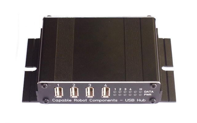
The Programmable USB Hub is designed to be durable and robust. The standard version has a robust extruded aluminum enclosure. The OEM version (board only) has corner mounting holes for easy integration into a custom enclosure. The Micro-USB connectors are reinforced, and all IO is protected from ESD strikes.
The locking input power connector features reverse polarity protection and over-voltage protection. The extruded aluminum enclosure for the Hub can be fitted with optional rubber bumper end caps or optional flange mounts.
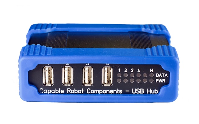
Optional Rubber Bumpers fit over the front and rear of the enclosure.
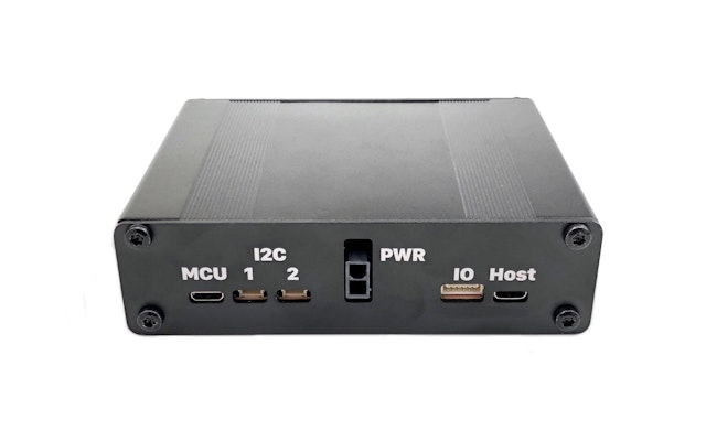
The power connector (Molex Mini-Fit Jr) locks into place and the micro-USB ports are reinforced.
Optional Mounting Flanges allow you to rigidly and permanently install the Hub in your environment.
The Programmable USB Hub is proudly open source. You can use MIT-licensed Python drivers to control and monitor your USB Hub the way you want to. The Hub can be easily integrated into hardware-in-the-loop (HITL) test systems and its’ in-built IO expansion allows the Hub itself to control or stimulate the Device Under Test (DUT). You can also automate testing of embedded USB devices - simulating USB unplug events and unexpected loss of USB power. Use the upstream USB port or the MCU USB port to control and monitor the USB hub.
Features
- 4x USB2 High Speed (480 mbps) downstream ports
- 1x USB2 High Speed (480 mbps) upstream port
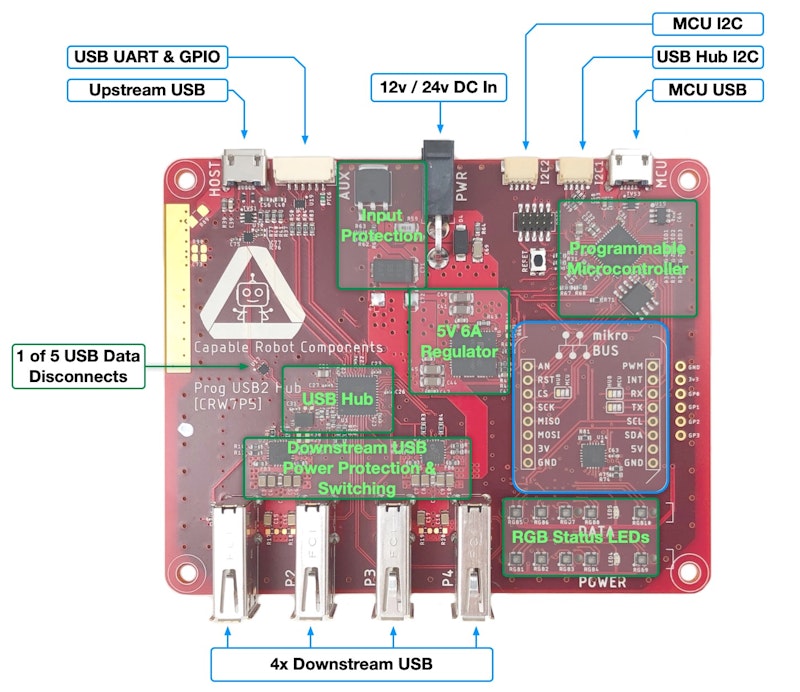
- 5th endpoint on USB hub exposes I2C, SPI, UART, and 2x GPIO
- Data lines to each USB port can be disconnected via software commands. This allows errant USB devices to be "unplugged" virtually and re-enumerated.
- USB digital signals can be boosted to help drive long cables.
- 5 V power on each downstream port can be individually turned on and off
- Monitor the power consumed by each port at up to 200 Hz at a resolution of 13 mA
- Adjustable (per-port) current limits between 0.5 A and 2.6 A
- Onboard regulator supports 12 V to 24 V power input and generates 6 A of 5 V power for downstream USB devices; both voltages can be monitored by the internal MCU. No power is drawn from the upstream USB port.
- Input power is protected from over-voltage events and reverse-polarity connection.
- mikroBUS header to add additional sensors and connectivity. Solder jumpers allow the UART and SPI pins to connect to either the USB hub or the MCU.
- JST GH connector with UART and 2x GPIO, controlled by the USB hub.
- 2x Sparkfun Qwiic connectors enable easy attachment of I2C sensors to the USB hub or to the internal MCU.
- 5x RGB status LEDs to visualize port power draw
- 5x RGB status LEDs to visualize port connection types
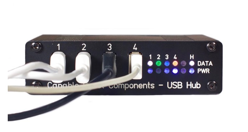
With the default firmware behavior, the Data LEDs show per-port data state with the following meaning:
- White : High speed device detected
- Green : Full speed device detected
- Blue : Low speed device detected
- Off : No downstream device detected
- Orange : Port data lines internally disabled / disconnected
The Power LEDs show per-port power draw in blue, with higher port power indicated with a brighter blue. Ports which have power turned off are lit orange.
Software
The Host Driver includes the following:
- A command line tool and python library which allows identification, communication, and control of an attached Hub.
- A Python API which allows Python & CircuitPython code to run on the host computer and communicate with SPI & I2C devices attached to the Hub.
- Example Python scripts & programs which allow you to read & control Port Data State, Port Power, and other functions.
For basic operation of the Hub, this host-side driver is not needed.
If you want to control or communicate with the Hub from the Host Computer, install Python and then the driver & CLI tool via pip:
pip install --upgrade capablerobot_usbhub
usbhub --help
Windows users will also need to run the following commands to correctly associate the USB Hub and underlying drivers:
pip install capablerobot_usbregister
usbregister device usbhubFor environments where Windows computers are not connected to the internet, an offline installer for the host-side driver has been created.
This installer include the USB Hub Host-Side Driver, Python 3.8.2, and required Python packages. It also automatically associate the USB Hub and underlying drivers during the installation process (e.g. you do not need to run the "usbregister" command yourself).
The CircuitPython-based firmware configures the main USB Hub chip upon boot and runs the monitoring loop which controls the RGB LEDs on the Hub's front panel.
This repository (and the USB Hub itself) contains this open-source code which is a great starting place to customize the automatic behavior of your USB Hub.
- host/gpio.py : Control and report state of the Hubs’ two GPIOs.
- host/current.py : Report current of downstream devices using the Hub’s UCS2113 ICs and the I2C bridge.
- host/power.py : Enable and disable downstream port power.
- host/status.py : Report connection state, link speed, and power draw of each downstream port.
- host/oled_ssd1306.py : Control of an external I2C OLED display.
- host/spi.py : Report data from a BMI160 Click board installed into the mikroBUS header of the USB Hub, using the Hubs SPI bridging functonality.
- firmware/knock_demo.py : Firmware example which displays which side of the Hub was knocked on. Requires a BMI160 Click board (I2C interface) and an external I2C OLED display.
Specifications
| Physical | ||
|---|---|---|
| Dimensions | 110 x 30 x 90 mm | |
| Weight | 200 g | |
| Mounting | Rubber Feet | Supplied with rubber feet which can be applied to the case bottom. |
| Rubber Bumpers | Optional. Wraps front and rear of case with molded rubber caps. | |
| Mounting Flanges | Optional. Slides into dove-tail grooves on case sides and allows Hub to be hard-mounted with user-supplied screws or bolts. A T10 torx screwdriver is needed to remove case cover and allow access to dove-tail grooves. | |
| Power | ||
| Input Voltage | 24 V | Allowable range of 9 to 26 V. |
| Output Voltage | 5.1 V | |
| Input Power | 0 to 36 W | |
| Output Power | 0.53 to 2.67 A | Per channel limits can be set to 0.53, 0.96. 1.07, 1.28, 1.60, 2.13, or 2.67 A. Combined port power draw cannot exceed 6 A. |
| Handling | ||
| Ingress Protection | IP40 | |
| Operating Temperature | 0 to 40 C | |
| Storage Temperature | -10 to 85 C | |
| Electrostatic Discharge | -6 to 6 kV | |
Regulatory Statements
USA/Canada: This equipment has been tested and found to comply with the limits for a Class A digital device, pursuant to Part 15 of the FCC Rules and ICES-003 Issue 6. These limits are designed to provide reasonable protection against harmful interference in a commercial & industrial environments.
This equipment generates, uses, and can radiate radio frequency energy, and if not installed and used in accordance with the instructions, may cause harmful interference to radio communications. However, there is no guarantee that interference will not occur in a particular installation. If this equipment does cause harmful interference to radio or television reception, which can be determined by turning the equipment off and on, the user is encouraged to try and correct the interference by one or more of the following measures:
- Reorient or relocate the receiving antenna.
- Increase the distance between the equipment and the receiver.
- Connect the equipment to an outlet on a circuit different from that to which the receiver is connected.
- Consult the dealer or an experienced radio/TV technician for help.
- In order to maintain compliance with FCC regulations, shielded cables must be used with this equipment. Operation with non-approved equipment or unshielded cables is likely to result in interference to radio and TV reception.
UL: Power supply listed as QQJQ.E183223
EU: Capable Robot Components, Inc. declares under our sole responsibility that the product name Programmable USB Hub (model CRZRYC) to which this declaration relates is in conformity with the essential requirements and other relevant requirements of the following standards and/or normative documents:
- 2014/30/EU : Electromagnetic Compatibility Directive
- 2011/65/EU : Restriction of Use of Hazardous Substances (RoHS) Directive
- EN 55032:2012 : Conducted Emissions, Mains Ports & Radiated Emissions Class A
- EN 55035:2017 : Immunity Requirements :
- IEC 6100-4-2:2008 : Electrostatic Discharge
- IEC 6100-4-3:2006/A1:2007/A2:2010 : Radiated Immunity
- IEC 6100-4-4:2012 : EFT/Burst, Power Ports and I/O Ports
- IEC 6100-4-5:2005 : Surge Immunity, Power Ports
- IEC 6100-4-6:2008 : Conducted Immunity, Power Ports and I/O Ports
- IEC 6100-4-11:2004 : Voltage Dips and Interrupts
Technical file held by : Capable Robot Components, Inc